In this article:
This post initiates a series demonstrating network layer 2 exploitation and protection techniques from practical point-of-view.
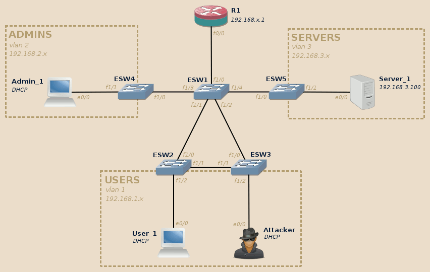
This series will rely on the following topology (click to enlarge):

This topology is composed of three VLANs:
- Users (VLAN 1) and Admins (VLAN 2) both contain end-user workstations, they are isolated from each other.
- Both can access machines located in Servers (VLAN 3).
The attacker is connected to the Users VLAN.
In this series we will see how the attacker can leverage various layer 2 configuration weaknesses to disrupt the network, hop from one VLAN to another, and intercept users communication, independently of their location in the topology.
We will limit ourselves to basic techniques as an attempt to demonstrate that pwning a insufficiently secured network doesn’t involve any high technology or knowledge. When appropriate we will also see how the attacks can be generalized to other real-life scenarios.
Creating the topology
This topology can be implemented using virtual machines and/or real gears.
Virtual lab
On my side I use GNS3 to easily build such infrastructure without having to worry about the multiple issues which come with real gear (availability, space, etc.).
For more information on how to setup the devices in a virtual lab, you may want to check the various tutorials available in lab section.
I recommend to build two versions of the same topology:
-
One using Dynamips virtualized routers to act as the switches.
-
The other one using IOU emulated switches.
Warning
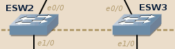
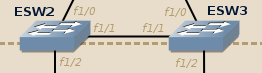
As IOU (sadly!) doesn’t tolerate loops in the topology, you will have to remove the link between ESW2 and ESW3 in your IOU-based topology:
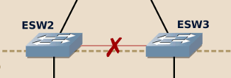
If you don’t do this, as soon as one of the end-device sends an ARP broadcast the IOU devices will enter in a broadcast storm and consume 100% of your CPU.

The other component will remain the same in both topology versions.
Due to the limitation of each solution, some attacks or mitigation techniques will be possible only in one version of the lab. I will mention the compatible version throughout the posts series.
Real gears
Using real gears is the most perfect solution to reproduce real-world environments. You can rely on the IOU switches configuration commands taking advantage of DTP and adapt them to your hardware.
If you are short of devices, you won’t need the complete topology to be available at any given time. I will indicate the required devices at the beginning of each post so you can focus on the devices required for each part.
Moreover, ESW2 and ESW3 switches can be merged into a single switch without any major impact. If possible however, I recommend to keep them both with the redundant link between them to get the most value out these labs.
Setting up devices
IOU-based ethernet switches
The following commands apply to switches emulated using IOU. They can also be used with real gear.
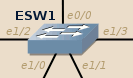
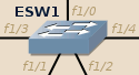
ESW1 is the core switch:
- All its interfaces are in trunk mode.
- It is explicitly set as the STP primary root on all VLANs.
 ESW1 configuration (IOU version):
1 2 3 4 5 6 7 8 9 10 11 12 13 14 15 | conf t interface range ethernet 0/0, ethernet 1/0 - 3 switchport trunk encapsulation dot1q switchport mode trunk exit vtp domain WWWOLF vlan 2 name admins exit vlan 3 name servers exit spanning-tree vlan 1-3 root primary end copy running-config startup-config |
 ESW2 and ESW3 configure themselves automatically thanks to the DTP protocol (plug-and-play).
Warning
When using IOU, don’t forget to remove the direct link between ESW2 and ESW3.
This warning does not apply for real gear.
SW4 and SW5 provide access to their own VLAN:
-
 SW4 configuration (IOU version):
1
2
3
4
5
conf t
    interface range ethernet 1/0 - 3
        switchport access vlan 2
        end
copy running-config startup-config
-
 SW5 configuration (IOU version):
1
2
3
4
5
conf t
    interface range ethernet 1/0 - 3
        switchport access vlan 3
        end
copy running-config startup-config


Router-based ethernet switches
The following commands apply to c3725/c3745 routers equipped with an EtherSwitch module to emulate switch devices.
ESW1 is the core switch:
- All its interfaces are in trunk mode.
- It is explicitly set as the STP primary root on all VLANs.
 SW1 configuration (router-based version):
1 2 3 4 5 6 7 8 9 10 11 12 13 14 15 16 17 | conf t interface range fastEthernet 1/0 - 4 switchport trunk encapsulation dot1q switchport mode trunk exit vtp domain WWWOLF vlan 2 name admins exit vlan 3 name servers exit spanning-tree vlan 1 root primary spanning-tree vlan 2 root primary spanning-tree vlan 3 root primary end copy running-config startup-config |
With real Catalyst switches and IOU-based ones, ESW2 and ESW3 work by default thanks to the DTP protocol. Router-based ethernet switches however do not support DTP (security-wise it is better that way…), so we need to configure them manually:
 ESW2 and ESW3 configuration (router-based version):
1 2 3 4 5 6 7 | conf t vtp mode client interface range fastEthernet 1/0 - 1 switchport trunk encapsulation dot1q switchport mode trunk end copy running-config startup-config |
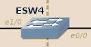
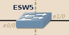
ESW4 and ESW5 provide access to their own VLAN (and the trunk port needs to be manually configured still due to the lack of DTP):
-
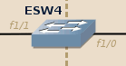 ESW4 configuration (router-based version):
 1
 2
 3
 4
 5
 6
 7
 8
 9
10
conf t
    vtp mode client
    interface range fastEthernet 1/1 - 15
        switchport access vlan 2
        exit
    interface fastEthernet 1/0
        switchport trunk encapsulation dot1q
        switchport mode trunk
        end
copy running-config startup-config
-
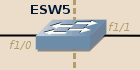 ESW5 configuration (router-based version):
 1
 2
 3
 4
 5
 6
 7
 8
 9
10
conf t
    vtp mode client
    interface range fastEthernet 1/1 - 15
        switchport access vlan 3
        exit
    interface fastEthernet 1/0
        switchport trunk encapsulation dot1q
        switchport mode trunk
        end
copy running-config startup-config


R1: main router
The main router provides the following services:
- Inter-VLAN routing.
- DHCP server for the VLANs 1 and 2 (the clients are given an address belonging to the [*.100-*.199] range).
- Firewall blocking any direct communication between VLAN 1 and VLAN 2.
 R1 configuration:
1 2 3 4 5 6 7 8 9 10 11 12 13 14 15 16 17 18 19 20 21 22 23 24 25 26 27 28 29 30 31 32 33 34 35 36 37 38 39 40 41 42 43 44 45 46 47 48 49 50 51 52 53 54 55 56 57 58 59 60 61 | conf t ! Firewall configuration class-map type inspect match-any ALL match protocol tcp match protocol udp match protocol icmp exit policy-map type inspect INSPECT_ALL class type inspect ALL inspect exit exit zone security USERS exit zone security ADMINS exit zone security SERVERS exit zone-pair security USERS-SERVERS source USERS destination SERVERS service-policy type inspect INSPECT_ALL exit zone-pair security ADMINS-SERVERS source ADMINS destination SERVERS service-policy type inspect INSPECT_ALL exit ! Interfaces configuration: interface fastEthernet 0/0 no shutdown exit interface fastEthernet 0/0.1 zone-member security USERS encapsulation dot1Q 1 ip address 192.168.1.1 255.255.255.0 exit interface fastEthernet 0/0.2 zone-member security ADMINS encapsulation dot1Q 2 ip address 192.168.2.1 255.255.255.0 exit interface fastEthernet 0/0.3 zone-member security SERVERS encapsulation dot1Q 3 ip address 192.168.3.1 255.255.255.0 exit ! DHCP server configuration: ip dhcp excluded-address 192.168.1.0 192.168.1.99 ip dhcp excluded-address 192.168.1.200 192.168.1.255 ip dhcp pool VLAN1 network 192.168.1.0 255.255.255.0 default-router 192.168.1.1 ! Normally you would also set the DNS server here. exit ip dhcp excluded-address 192.168.2.0 192.168.2.99 ip dhcp excluded-address 192.168.2.200 192.168.2.255 ip dhcp pool VLAN2 network 192.168.2.0 255.255.255.0 default-router 192.168.2.1 exit end copy running-config startup-config |
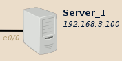
Server_1: a shared web server
 On my side I will use Bitnami Wordpress image to act as the server.
Feel free to use anything you like, as long as there is some data to intercept.
On my side I will use Bitnami Wordpress image to act as the server.
Feel free to use anything you like, as long as there is some data to intercept.
1 2 3 4 5 6 7 8 9 10 11 12 13 14 15 16 17 18 19 20 21 22 23 24 25 26 27 28 29 30 31 32 | # If you need to change the keyboard layout (French layout here): sudo loadkeys fr # To get a root shell (ONLY FOR LAB PURPOSES!) sudo -s ifconfig eth0 192.168.3.100 # Avoid bug (?) from IOU by reducing the MTU to leave enough room # for the 802.1q VLAN tag (4 bytes), otherwise IOU drops large # packets outgoing the trunk interface with the error: # "LINK-4-TOOBIG: Interface Ethernet0/0, Output packet size of 1518 bytes too big" ifconfig eth0 mtu 1496 route add default gw 192.168.3.1 vi /etc/network/interfaces # [...skipped...] auto eth0 iface eth0 inet static address 192.168.3.100/24 gateway 192.168.3.1 mtu 1496 # [...skipped...] vi /etc/hosts 127.0.0.1 localhost 192.168.3.100 bitnami # Force Apache to listen on the IPv4 interface instead of IPv6 ones vi /opt/bitnami/apache2/conf/httpd.conf # [...skipped...] # Listen 80 Listen 0.0.0.0:80 # [...skipped...] # To restart the services: service bitnami restart |
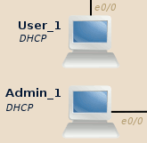
User_1, Admin_1: clients
 For them on my side I will use GNS3’s Firefox appliance.
It is a super-light graphical Linux with Firefox.
For them on my side I will use GNS3’s Firefox appliance.
It is a super-light graphical Linux with Firefox.
- When creating the end-device template, don’t forget to edit the Qemu
options:
-vga std -usbdevice tablet -k fr. - You have an icon in the dock to set the keyboard layout on the first boot.
Ensure that User_1 and Admin_1 can both open http://192.168.3.100 in their browser:

Attacker: the source of all evil
 I will use BackBox Linux.
If you are more comfortable with another distribution, feel free to use it
instead.
We will mostly work with Yersinia and Ettercap, ensure you have them
available on your system.
I will use BackBox Linux.
If you are more comfortable with another distribution, feel free to use it
instead.
We will mostly work with Yersinia and Ettercap, ensure you have them
available on your system.
Attacker can ping User_1 but cannot ping Admin_1:
backbox@backbox:~$ ping -c 1 192.168.1.100
PING 192.168.1.100 (192.168.1.100) 56(84) bytes of data.
64 bytes from 192.168.1.100: icmp_seq=1 ttl=64 time=0.919 ms

--- 192.168.1.100 ping statistics ---
1 packets trasmitted, 1 received, 0% packet loss, time 0 ms
rtt min/avg/max/mdev = 0.919/0.919/0.919/0.OOO ms
backbox@backbox:~$ ping -c 1 192.168.2.100
PING 192.168.2.100 (192.168.2.100) 56(84) bytes of data.

--- 192.168.2.100 ping statistics ---
1 packets trasmitted, 0 received, 100% packet loss, time 0 ms

backbox@backbox:~$
He also has access to Server_1.

Next: Practical network layer 2 exploitation: passive reconnaissance
Network layer 2 practical offensive and defensive security: listen and learn from network's white noise.

