
In this article:
NTP allows to synchronize the clock of various devices to a common reference.
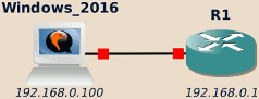
In this how-to, we will configure a Windows Server as a NTP server and a Cisco IOS-based router to act as a NTP client. We will also see how to configure the router so it can itself serve as server to other devices, thus acting as an NTP relay.

Windows (NTP server)
Windows does not ship with any NTP server by default. In fact, Windows’ W32Time service implements SNTP instead, which is not compatible with NTP clients (see here).
Meinberg NTP is a commonly used alternative to get a proper NTP server on Windows, and is the one we will use in this how-to.
Before installing it, check that the following settings are correct:
- The IP configuration (192.168.0.100 in my case)
- Check the current time (08h15 in my case, but who cares?)
Once this is done, install Meinberg NTP server and, at the end of the installation process, edit its configuration file1 to allow NTP clients source addresses and define the time sources. Here we add 192.168.0.1 as the only alowed client and force the NTP server to use the local clock and consider it safe (in the real world you would use upstream NTP servers instead):
1 2 3 4 5 6 7 | # Allow requests from 192.168.0.1 restrict 192.168.0.1 # Rely on local system clock and force it as safe. # ONLY FOR LAB PURPOSES! server 127.127.1.0 prefer fudge 127.127.1.0 stratum 12 |
Warning
Don’t forget the prefer keyword above (it is missing in the default
proposed settings).
Otherwise, the NTP server will consider the time as unsafe and clients will
not sync with it (see the “stratum 0” issue below).
Note
If the NTP service fails to start, it probably means that the Microsoft Visual Studio Redistributable libraries are not installed on your system.
They are freely available from Microsoft website.
Once NTP server is installed, the NTP port (UDP 123) should be open on every network interface:
C:\Users\Administrator>netstat -an | findstr 123
  UDP    0.0.0.0:123            *:*
  UDP    127.0.0.1:123          *:*
  UDP    192.168.0.100:123      *:*
  UDP    [::]:123               *:*
  UDP    [::1]:123              *:*
  UDP    [fe80::a8ef:96af:5ed4:7607%5]:123  *:*

C:\Users\Administrator>
The last step is now to configure the Windows Firewall to allow incoming NTP connections:
- From Windows’ Settings or Control Panel, open the Windows Firewall settings.
- On the left pane, click on the Allow an app or feature through the Windows Firewall link.
- If ntpd is not already in the list, click on the Allow another app… button and browse to C:\Program Files (x86)\NTP\ntpd.exe.
- Check the boxes to allow ntpd to access the network.
Cisco IOS-based router (NTP client)
Enabling NTP client on Cisco IOS-based devices
When booting the router, you may need to manually adjust the time the first time to reduce the gap with the NTP server’s time.
R1#show clock
*00:00:18.403 UTC Fri Mar 1 2002
R1#conf t
Enter configuration commands, one per line.  End with CNTL/Z.
R1(config)#clock timezone UTC +2
R1(config)#
*Mar  1 00:00:34.943: %SYS-6-CLOCKUPDATE: System clock has been updated from 00:00:34 UTC Fri Mar 1 2002 to 02:00:34 UTC Fri Mar 1 2002, configured from console by console.
R1(config)#clock summer-time CEST recurring
R1(config)#
*Mar  1 00:00:50.431: %SYS-6-CLOCKUPDATE: System clock has been updated from 02:00:50 UTC Fri Mar 1 2002 to 02:00:50 UTC Fri Mar 1 2002, configured from console by console.
R1(config)#end
R1#
*Mar  1 00:00:57.671: %SYS-5-CONFIG_I: Configured from console by console
R1#clock set 08:22:00 Oct 06 2017
R1#
*Oct  6 05:22:00.000: %SYS-6-CLOCKUPDATE: System clock has been updated from 02:01:41 UTC Fri Mar 1 2002 to 08:22:00 CEST Fri Oct 6 2017, configured from console by console.
R1#sh clock
08:22:08.779 CEST Fri Oct 6 2017
R1#
If it not already done, set an IP address to the router:
R1#conf t
Enter configuration commands, one per line.  End with CNTL/Z.
R1(config)#int fa0/0
R1(config-if)#ip add 192.168.0.1 255.255.255.0
R1(config-if)#no shut
R1(config-if)#end
R1#
Oct  6 05:23:17.463: %SYS-5-CONFIG_I: Configured from console by console
R1#
Oct  6 05:23:18.235: %LINK-3-UPDOWN: Interface FastEthernet0/0, changed state to up
Oct  6 05:23:19.235: %LINEPROTO-5-UPDOWN: Line protocol on Interface FastEthernet0/0, changed state to up
R1#
Then NTP can now be enabled on the router:
R1#conf t
Enter configuration commands, one per line.  End with CNTL/Z.
R1(config)#ntp server 192.168.0.100
R1(config)#end
R1#
Oct  6 05:23:52.647: %SYS-5-CONFIG_I: Configured from console by console
R1#copy run start
Destination filename [startup-config]?
Building configuration...
[OK]
R1#
Synchronization between the client and server may take a few dozen seconds,
potentially a few minutes depending on the gap between the client and server
time.
Eventually, the show ntp status command should indicate that the client is
now synchronized:
R1#show ntp status
Clock is synchronized, stratum 14, reference is 192.168.0.100
nominal freq is 250.0000 Hz, actual freq is 250.0000 Hz, precision is 2**18
reference time is DD81A03E.532D3EE6 (09:25:02.324 CEST Fri Oct 6 2017)
clock offset is -0.4366 msec, root delay is 29.89 msec
root dispersion is 199.91 msec, peer dispersion is 0.64 msec
R1#
NTP details go as follows:
R1#show ntp associations detail
192.168.0.100 configured, our_master, sane, valid, stratum 13
ref ID 127.127.1.0, time DD81A05F.4DB61861 (09:25:35.303 CEST Fri Oct 6 2017)
our mode client, peer mode server, our poll intvl 64, peer poll intvl 64
root delay 0.00 msec, root disp 73.85, reach 377, sync dist 90.790
delay 8.94 msec, offset -13.0067 msec, dispersion 12.47
precision 2**17, version 3
org time DD81A07E.483C9202 (09:26:06.282 CEST Fri Oct 6 2017)
rcv time DD81A07E.4CB6196C (09:26:06.299 CEST Fri Oct 6 2017)
xmt time DD81A07E.4A5E59F5 (09:26:06.290 CEST Fri Oct 6 2017)
filtdelay =     8.94   32.61   32.94   33.66   32.59   33.42   32.75   29.89
filtoffset =  -13.01   -0.11   -0.01   -0.73   -0.73   -1.13   -1.39   -0.44
filterror =     0.02    0.99    1.01    1.02    1.04    1.05    1.07    1.08

R1#
Troubleshooting
IOS may be a bit… temperamental sometimes. If anything goes wrong its diagnose is to blame the NTP server’s sanity.
Well, with good will on both side I’m sure it is possible to get things running, don’t you agree R1? Here are a few common causes of “insane” NTP server and how to solve them.
Failed connection
Here is an example of such “insane” NTP server:
R1#show ntp associations detail
192.168.0.100 configured, insane, invalid, unsynced, stratum 16
ref ID 0.0.0.0, time 00000000.00000000 (01:00:00.000 CET Mon Jan 1 1900)
our mode client, peer mode unspec, our poll intvl 64, peer poll intvl 64
root delay 0.00 msec, root disp 0.00, reach 0, sync dist 0.000
delay 0.00 msec, offset 0.0000 msec, dispersion 16000.00
precision 2**5, version 3
org time 00000000.00000000 (01:00:00.000 CET Mon Jan 1 1900)
rcv time 00000000.00000000 (01:00:00.000 CET Mon Jan 1 1900)
xmt time 00000000.00000000 (01:00:00.000 CET Mon Jan 1 1900)
filtdelay =     0.00    0.00    0.00    0.00    0.00    0.00    0.00    0.00
filtoffset =    0.00    0.00    0.00    0.00    0.00    0.00    0.00    0.00
filterror =  16000.0 16000.0 16000.0 16000.0 16000.0 16000.0 16000.0 16000.0

R1#
In the show ntp associations detail command output, pay special attention to
the following lines:
- org time: Originator time, this was the time on NTP server side when the packet was created.
- rcv time: Receive time, this was the time on client (router) side when the NTP packet was received.
Here everything is left to the UNIX Epoch. This output is normal just after a change in the local clock or NTP settings but shouldn’t last more than a minute. If it persists, this output usually means that the NTP client was not able to contact the server: check IPs affectation, that the ports are listening and that both the NTP server settings and the system firewall allow the connection.
Large time gap
R1#show ntp associations detail
192.168.0.100 configured, insane, invalid, unsynced, stratum 16
ref ID 0.0.0.0, time 00000000.00000000 (01:00:00.000 CET Mon Jan 1 1900)
our mode client, peer mode unspec, our poll intvl 64, peer poll intvl 64
root delay 0.00 msec, root disp 0.00, reach 0, sync dist 0.000
delay 0.00 msec, offset 0.0000 msec, dispersion 16000.00
precision 2**5, version 3
org time DD80F1B4.A569FCA6 (20:00:20.646 CEST Thu Oct 5 2017)
rcv time DD81103A.61A40826 (22:10:34.381 CEST Thu Oct 5 2017)
xmt time DD81103A.5C278DB1 (22:10:34.359 CEST Thu Oct 5 2017)
filtdelay =     0.00    0.00    0.00    0.00    0.00    0.00    0.00    0.00
filtoffset =    0.00    0.00    0.00    0.00    0.00    0.00    0.00    0.00
filterror =  16000.0 16000.0 16000.0 16000.0 16000.0 16000.0 16000.0 16000.0

R1#
Here the time difference between the router and the NTP server is too large, the router consider this suspicious and refuses to sync. Check your clock settings both on server and client, including the timezone settings.
The “stratum 0” issue
Everything looks normal in the NTP association details but the router sticks
to consider the NTP server as insane?
Dig deeper and check the actual NTP packet using debug ntp packets:
R1#debug ntp packets
NTP packets debugging is on
R1#
.Oct  5 21:50:58.855: NTP: xmit packet to 192.168.0.100:
.Oct  5 21:50:58.855:  leap 3, mode 3, version 3, stratum 0, ppoll 64
.Oct  5 21:50:58.859:  rtdel 0000 (0.000), rtdsp 10001 (1000.015), refid 00000000 (0.0.0.0)
.Oct  5 21:50:58.859:  ref 00000000.00000000 (01:00:00.000 CET Mon Jan 1 1900)
.Oct  5 21:50:58.859:  org DD812783.1FF77E54 (23:49:55.124 CEST Thu Oct 5 2017)
.Oct  5 21:50:58.859:  rec DD812782.E3781608 (23:49:54.888 CEST Thu Oct 5 2017)
.Oct  5 21:50:58.863:  xmt DD8127C2.DB1FEA78 (23:50:58.855 CEST Thu Oct 5 2017)
.Oct  5 21:50:58.871: NTP: rcv packet from 192.168.0.100 to 192.168.0.1 on FastEthernet0/0:
.Oct  5 21:50:58.871:  leap 3, mode 4, version 3, stratum 0, ppoll 64
.Oct  5 21:50:58.871:  rtdel 0000 (0.000), rtdsp 0274 (9.583), refid 494E4954 (73.78.73.84)
.Oct  5 21:50:58.871:  ref 00000000.00000000 (01:00:00.000 CET Mon Jan 1 1900)
.Oct  5 21:50:58.871:  org DD8127C2.DB1FEA78 (23:50:58.855 CEST Thu Oct 5 2017)
.Oct  5 21:50:58.871:  rec DD8127C3.1C069047 (23:50:59.109 CEST Thu Oct 5 2017)
.Oct  5 21:50:58.871:  xmt DD8127C3.1C116F97 (23:50:59.109 CEST Thu Oct 5 2017)
.Oct  5 21:50:58.871:  inp DD8127C2.DF3DEAF8 (23:50:58.872 CEST Thu Oct 5 2017)
See the stratum 0 output? This is no good.
The only allowed value over the network are ranging from 1 to 16, stratum 0 is used here2 as a mean to notify of a problem server side.
The most common issue is that the NTP server hasn’t access to any reliable time source:
-
If your server is configured to use upstream NTP servers, check the connectivity with them, in particular ensure that no firewall blocks the traffic on UDP port 123.
-
If, for testing purposes, your NTP server is meant to rely on the local system time instead of using remote trusted source, you must use the
preferkeyword to explicitly force the NTP to act this way (this isn’t enabled by default as, on production environments, you don’t want a NTP server to silently switch to local system time).
Other
The debug ntp validity commands offers a way to ask the IOS NTP client why
server information is rejected:
R1#debug ntp validity
NTP peer validity debugging is on
R1#
.Oct  5 21:50:58.871: NTP: packet from 192.168.0.100 failed validity tests 20
.Oct  5 21:50:58.871: Peer/Server Clock unsynchronized
R1#
Available rejection causes are listed on Cisco website, along with other troubleshooting advices.
Note
When you are done investigating, don’t forget to disable debugging using the
no debug all command:
R1#no debug all
All possible debugging has been turned off
R1#
Enabling NTP server
Cisco IOS-based devices can also act as NTP servers or relays to propagate time information throughout your infrastructure.
Enabling the IOS NTP server is as simple as using the ntp master command in
configuration mode followed by the stratum number you desire:
R1#conf t
Enter configuration commands, one per line.  End with CNTL/Z.
R1(config)#ntp master 15
R1(config)#end
R1#
Oct  6 07:30:53.654: %SYS-5-CONFIG_I: Configured from console by console
R1#
Check you NTP associations: the local device should now appear as a selected NTP source (‘+’ symbol). Ensure that the remote NTP server is still the master (‘*’ symbol).
R1#show ntp association

    address         ref clock     st  when  poll reach  delay  offset    disp
*~192.168.0.100    127.127.1.0      13   293   512  377    23.8   22.17     7.2
+~127.127.7.1      127.127.7.1      14    17    64  377     0.0    0.00     0.0
* master (synced), # master (unsynced), + selected, - candidate, ~ configured
R1#
Warning
For some reason Cisco sets the default stratum to 8. If the upstream server has a higher stratum number, this means that the Cisco will switch to its internal clock and stop using the remote NTP server, which is usually not what you want.
I recommend to manually set the stratum number, as in the example above, and double-check you NTP associations.
-
The installer proposes to edit the configuration at the end of the installation process, in all cases the NTP configuration is stored in C:\Program Files (x86)\NTP\etc\ntp.conf. ↩
-
More information on NTP stratums is available here. While stratum 0 is normally reserved for local time devices, it is also used to handle error cases like in the case of the Kiss-of-Death packet. This is the usage we are facing here. ↩